
One can use multiple ways to calibrate a camera for MICA. Here, we present the “standard” and most thorough methdology:
Calibrating a Camera using a Monochromator and a Spectroradiometer
In essence, the process entails:
- Projecting a light beam of narrow bandwidth onto a diffuse white standard (e.g. spectralon 99%) using a monochromator.
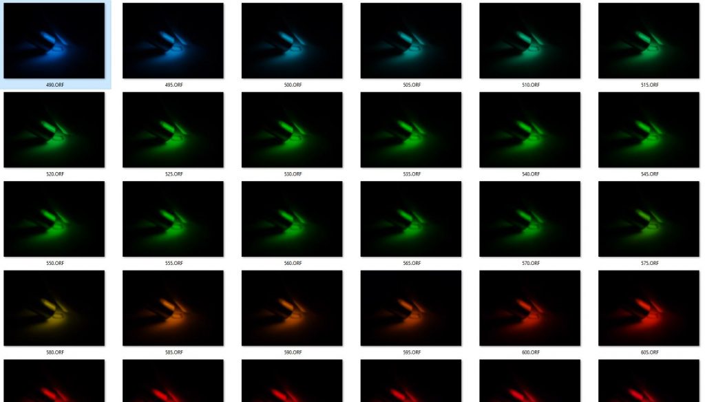
- Take a picture of that light spot with the camera to be calibrated (1picture/5nm).
- Take a measure of the light intensity (uW/cm^2/s) using a spectroradiometer (note this must be fully calibrated to account for the spectroradiometer’s sensitivity and absorbance by optical media, e.g. using a calibration light source or using a lab which can perform this).
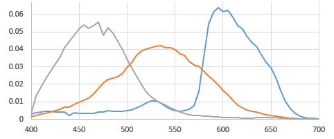
- Measure the linear R, G and B pixel value and correlate it to the spec measurement.
- Repeat for every 5nm to get entire 400-700nm spectral sensitivity of the camera (or 300-700nm for VIS-UV full spectrum cameras).
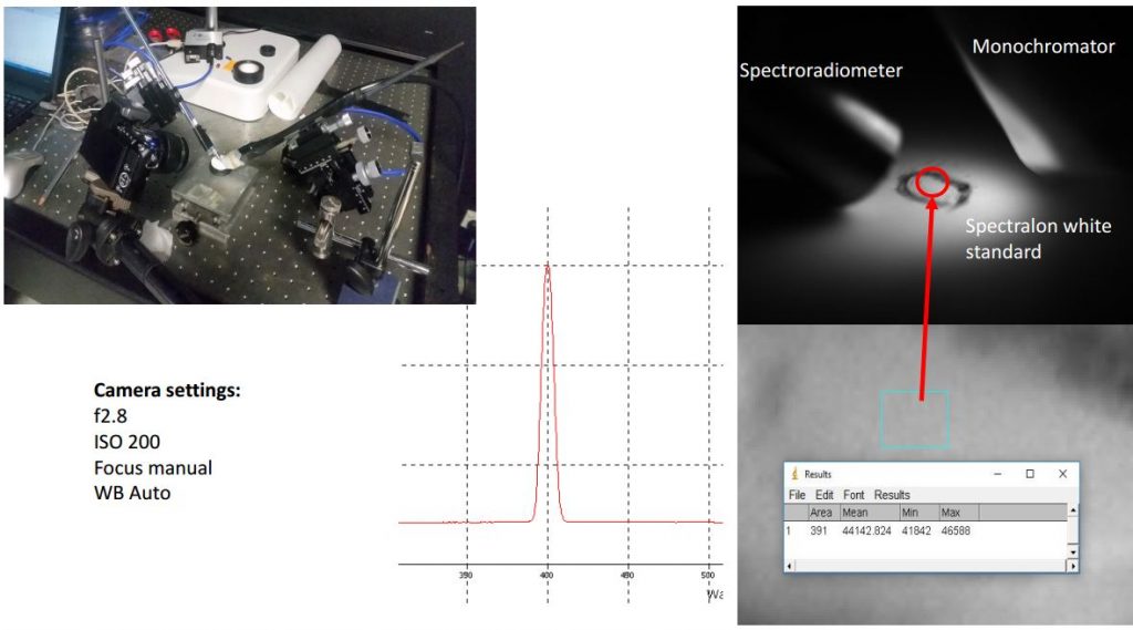
Figure 1: Setup on optical bench (needed for precision). Top left: USB2000 400nm fibre optic cable on the left, monochromator fibre on the right. Spectralon in the middle, camera fixed at lower center. Top right: Close up of spectralon white. Central area of illumination indicated with pencil circle as it can be hard to see sometimes. Bottom right: Average pixel response for one channel. Center: Spec reading of 400nm monochromator light. Bottom left: settings used for the Olympus E-Pl5.
Detailed Instructions:
I. Setup of Hardware (See Fig 1):
You will have to work on an optic bench to be able to hold everything in place and get exact readings. Get an absolutely clean and unsratched spectralon 99% reflectance standard (Sand it down with a wet 200 or 400 (better) grid sandpaper and let it dry). Grab a piece of black electric tape and punch a hole with a hole punch. Place the punctured tape on the spectralon standard so that the hole is in the center.
Get 3 sockets to fix the recording sensors around the standard (Fig1). You will need 2 sockets for holding a plastic rod in place to which either the output fibre of the monochromator or the recording fibre (400nm, non-bifurcated cable) is taped to so it will absolutetly not move. The third socket will be used to fix the camera in place. Slightest shifts will induce large variations in your recordings and make your measurements useless. Position the monochromator, camera and the optic fibre as depicted in Fig 1. Essentially with the monochromator and spec cables almost touching the white standard.
Disclaimer: If you don’t have a calibration file for the specific USB2000 unit and the specific cable you are working with you will need to create one prior to the camera calibration. It’s a pain to figure it out but is quickly done once you know how to.
II. Setup of Camera
The camera calibration will have to be done with a lens that can’t zoom. If your camera is able to zoom (either by built-in or added lenses) you will need to ensure that all your images will be taken with identical zoom settings. The reason for this being that physical zoom distorts the optic properties of the lens and subsequently messing up your calibration. Note that this means that any images will have to be taken with the exact same zoom settings and lenses once you have calibrated the camera.
Your white balance can be set to automatic as the linearisation and normalisation of the images in the MICA toolbox will correct for that. Your apperture (f-value) will need to be fixed. I recommend using exposure bracketing to avoid taking overexposed images. In any case, choose the settings on your camera that allow you to see the exposure histogram. This will greatly help to avoid overexposure. You will need to record the shutterspeed of each image. Your ISO will need to be fixed e.g. at 200, which is reasonable (also when you are taking images in the field). I recommend taking images using exposure bracketing to ensure optimal exposure. This is crucial as the brighntess of the monochromator varies substantially across the light spectrum. You will likely have t play around with this for a while.
III. Analysing the measurements
The idea is to have a series of images for which you know exactly how long (exposure time) the sensors have been exposed to a certain number of photons (sum of absolute irradiance measured by the spectrophotometer) and what pixel value (RGB value) that stimulation corresponds to.
So, on one hand you will need a well exposed (bright enough but not overesposed) series of images of the light spot of the monochromator on the spectralon white every 5nm from 400nm-700nm (Or other depending on your needs, e.g if your camera can detect UV). On the other hand you need the corresponding absolute irradiance measurements.
Using the MICA toolbox you can open your .RAW images using the DCRaw plugin (Plugins > micaToolbox > Tools > DCRAW Import). This will open your image as a linearised image. Using the circular polygon selection tool you can then select the illuminated spot. Don’t worry, all we need is a couple of dozen pixels at the minimum, so you don’t need to select the ENTIRE spot precisely. Just the most homogeneously illuminated bit in the center. Select the ROI by pressing ‘t’ (Or whatever letter you fancy, other than ‘s’ which is for size standards specifically). Then press “m” to measure the current selection. Record the average of the reading for each channel (R, G and B). Divide this value by your shutter speed (e.g. 0.05) and this will give you your normalised pixel response. Note that you want the exact integration time of the exposure. e.g. 1/1000th of a second is normally actually 1/1024 and the times often follow this base-2 system. Divide this value by the sum of the absolute irradiance from 400nm-700nm. This is how sensitive your R, G and B sensors in your camera are to light at a given wavelength. This value does not have any units (X amount of Light per time divided by X amount of light per time). Interpolate using R or Matlab to transform this 5nm bracketing to 1nm measures. Normalise these values to Max=1 or Sum=1 according to the requirements of the calculations you use these for. Assuming you will be using it for MICA you will find the file specifications in the MICA manual.