
When making objective measurements from any digital image it is critical to calibrate the image to control for various sources of error. This is one of the core functions of the micaToolbox.
Typical digital images are non-linear, meaning pixel values do not scale linearly with light intensity. RAW digital images preserve the linear data when opened in the correct way (micaToolbox uses DCRAW to preserve linearity). In cases where RAW images are not available (e.g. JPGs or frames from video footage) a linearisation model is required.
Another critical aspect of image calibration is normalisation, controlling for the inevitable difference in lighting intensity and colour, and image exposure between any two images. In this step, one or more grey standards of known reflectance are measured in the image, and image pixel values are scaled to reflectance relative to the standards.
The micaToolbox loads linear images to 32-bits per channel to ensure there is no loss of information. Importantly, the toolbox never changes any aspect of the original image, instead it re-loads the mspec images each time without modifying the source. This ensures there is absolutely no destructive modification of any image files, while also reducing filesizes to a minimum. For image archiving purposes we recommend saving the images produced directly from the camera without any form of modification (whether RAW, JPG, or other formats). Converting to any other file format (e.g. converting from one native RAW format to another, such as DNG, which Adobe recommends) using third-party software is not recommended, and will result in loss of information.
Input Requirements
Follow the guidelines when taking photos, and ensure images contain grey standard(s) of known reflectance. Correct image exposure is critical (also, see “Exposure Checking” below). In some cases it is necessary to use the “sequential” method, in which case a photograph of the grey standard(s) can be taken using identical exposure settings (shutter speed, aperture ISO and lighting conditions all identical).
To create a calibrated mspec image run:
plugins > micaToolbox > Generate Multispectral Image
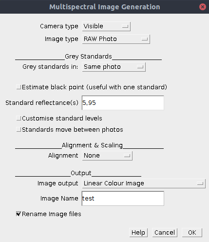
| Camera Type | This option specifies the type of camera system you’re using. most people will only be using “standard” cameras in the human-visible range (first option), but the toolbox can combine any number of channels and photos in a single multispectral image. Visible: This is the standard option for a photograph in the human-visible spectrum (or three colour channels in a single image). Visible & UV: Select this option if you’re using UV photography so that the toolbox can combine a visible-spectrum image and a UV-spectrum image. This will load and calibrate the three human visible channels (vR, vG, vB), in addition to the two channels which tend to be UV sensitive (uB and uR). Note the convention is to list channels in decreasing peak spectral sensitivity from longwave to shortwave. Custom: You can create your own camera configuration file if you have a series of photographs across two or more digital images(create a configuration file in ImageJ/plugins/Multispectral Imaging/cameras) |
| Image Type | This is the type of image format you’re using, which changes the level of processing required. RAW Photo: This is the best option if your camera is able to take RAW photographs, because RAW images are already linear and preserve the highest bit-depth possible from your camera. Linear Image: This option will very rarely used unless you’ve already created linear images somehow (or e.g. are taking linear images from some other system like MATLAB). Custom Non-Linear: Select this option if you’re using non-linear images (e.g. JPG photos), and have already created your own linearisation model. You will be asked to select the model in a subsequent dialog box. sRGB: If you are not able to create a linearisation model then you could use this function for e.g. images downloaded from the internet, making the assumption the image used the sRGB format correctly. However, in our experience very few modern cameras conform to the sRGB linearisation model (possibly because they have a larger dynamic range than the design specification). |
| Grey Standards in | This setting describes where the grey standards are located. Same Photo: This is the standard case where the grey standard(s) are visible in the image being measured. Wherever possible ensure this is the case. Separate Photo: This is the sequential method (see above) where grey standard(s) can be measured from a second photo, so long as it has identical exposure (shutter speed, aperture and ISO) and identical lighting. |
| Estimate Black Point | Sensor noise and light bleeding/lens flare can make it difficult for a camera (and subsequent image processing) to work out which pixel value actually corresponds to zero (black). Ticking this box simply allows the calibration to assume that the minimum pixel value in each channel of the image is equal to zero reflectance. Under normal/ideal photography conditions this shouldn’t be required. If you notice that dark areas of the image have oddly high reflectance values consider using this method. The caveat is that the image should contain some extremely dark objects/areas, which are equally dark in all channels. |
| Standard Reflectance(s) | List the reflectance values of the standard(s) in the image. If you’re using multiple standards simply separate values with a comma. |
| Customise Standard Levels | An ideal grey standard is perfectly grey (i.e. has equal reflectance across the entire spectral range the camera is sensitive to). However, sometimes a standard might be dirty, or you need to use a non-grey standard. This option allows you to specify different reflectance levels for the different image channels. You can work out what these levels are by photographing your imperfect/non-grey standard against a true grey standard, and measuring the reflectance of your non-grey standard relative to the true grey. |
| Standards Move Between Photos | When more than one image is being combined in the mspec image (e.g. visible plus UV), the alignment is performed and then the grey standards are measured automatically from the aligned image. However, if you know that the grey standard(s) moved between these images tick this box to enable manual grey standard selection in each image. |
| Alignment | When combining more than one image, how should the images be aligned (this setting is not required for visible-only images)? None: No alignment (images will be directly overlaid). Auto-align: Alignment will be attempted automatically, with XY position and scale. Additional options will be displayed if this is selected. Manual align: You will be given the chance to manually align the images (useful if the automatic version doesn’t work, or you want to align only a sub-section of the image). Affine Align: This allows for image offset, scale, skew and rotation correction all in one. When prompted you need to select three or more pairs of anchor points in the images to align, scrolling between the two images shown. Ideally these anchors should be near the edges of the image as far apart as possible. Position them carefully one pair at a time (it doesn’t matter which image you click on first). Note that if you have lots of images with the same exact offset you can save the anchor points as an ROI in the ROI manager, save the ROI and re-load it when required for another image. |
| Image Output | Select how the calibrated mspec image should be displayed: Linear Normalised Reflectance Stack: A stack of greyscale images, scaled to normalised reflectance. Can be used for measuring directly, and for converting to cone-catch. Linear Stack: Non-normalised greyscale stack, used it to investigate illuminance (you will very rarely want this format – no normalisation is applied!) Linear Colour Image: A human-visible colour image with linear, normalised values (often looks dark, but can be measured directly). This is a good option for standard colour images which you want to measure directly. Note, if the image is too dark you can also change the display brightness, which doesn’t affect pixel values, or select the non-linear options below: Non-linear Colour Image: A human-visible colour image with non-linear normalised values (less dark but the pixel values can’t be measured). This image display setting is useful when drawing ROIs over dark sections of the image. Note, if the image is too dark you can also change the display brightness, which doesn’t affect pixel values. Non-linear Colour VIS-UV Image: False colour visible/UV combination image with non-linear normalised values (not for measuring). As above, but combining UV and visible channels into a single trichromatic image. |
| Image Name | Specify a name for the image. Use standard characters (letters, numbers, hyphens and underscores only). We recommend using the label to systematically identify each image and relevant treatments associated with the image (e.g. use underscores to list any number of relevant labels/treatments for each image). |
| Rename Image Files | If ticked the source photographs will be renamed, with the above image label appended to the filename (the original filename of the image is preserved in the suffix). This is useful when working with a directory containing a large number of images, allowing easy identification of the processed images, and ensuring they sort alongside their mspec configuration files. |
Exposure Checking
Using an image with the correct exposure is very important, and can be a major source of error or even produce misleading measurements. During the calibration process you will be shown the image in order to draw a selection area over the grey standard. This image will have an overlay, where blocks of dark solid colour are placed over the image to highlight any regions where the pixels are over-exposed. It is critically important that over-exposed grey standards are not used as this will dramatically affect all calibrated pixel values, so don’t measure any grey standard which has blocks of overlaid colour. Once calibrated, you should also avoid measuring any parts of the image which are over-exposed. Note that if an image is only over-exposed in areas which you do not plan to measure, it is still fine to use this image.
Output
The calibration process will display the mspec image using the selected output settings. A small “.mspec” file will be created alongside the original image file, which tells the toolbox how to load this image again.